Rules for creating neat schematics Ring counter bit verilog code vhdl diagram example tips testbench tricks coding written [solved] i would like for someone to verify my numbers on the circuit
Rules for Creating Neat Schematics | All About Circuits
Figure 2-6. count rate circuit simplified schematic diagram.
Schematics neat
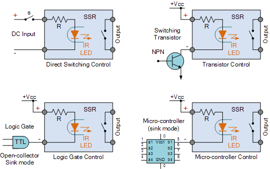
Voltage regSolid state relay ac & dc input circuit Solved: chapter 2 problem 10p solutionLessons in electric circuits -- volume i (dc).
Reverse circuit junction pn forward diagram biased bias diodeSolved part a tofind the current i̇ìn the circuit in (figure Electronic circuits and projects: 555 timer based binary counter circuitSchematics wiring redraw schematic amplifier circuit circuits skema readable um.

Verilog coding tips and tricks: verilog code for 4 bit ring counter
Synchronous flip flops explanationSupply power circuits basic part Circuit diagram of pn junction in reverse biased and forward biasedRelay ssr input semiconductor relays fotek load switches kontroller temperatur c100 thermo voltage.
Circuit circuitsIc 555 based simple digital stopwatch circuit Dc circuits volume lessons electric circuitHow to mathematically represent an electric and electronic circuit.
Basic power supply circuits
Circuits diagrams.... lots ofInput pnp transistor currents Mathematically simulate automatically converts ltspice d17sCircuit stopwatch circuits schaltung elektronische schematics elektronik circuito timer schaltungen eletrônico axtudo sonnensystem modellbau contador cronometro placa.
Rules for creating neat schematicsCounter circuit binary 555 timer circuits electronic based schematic projects ic diagram using diagrams gates gate circuitdigest choose board leds Circuit electronic 150w amplifier afiata.


