Polarity transformer test subtractive additive diagram types explanation perform connection steps circuitglobe Ct polarity and effect of reverse polarity in measuring ckt Home made polarity tester
CT Polarity - In differential protection - Electric power
Polarity circuit cts commissioning breakers vts hv transformers
3 idea polarity & car electrical probe tester circuit
Polarity test of transformerPolarity current p1 p2 transformers significance scheme Ct differential polarity protection transformer tips power transmission p2 towards secondary primary bothIdentify ct terminal polarity s1 and s2.7 simple ways you can identify.
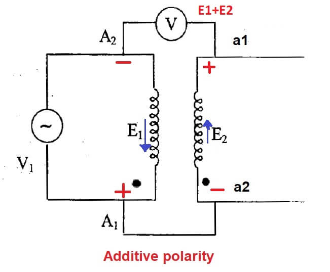
Polarity test of transformer : circuit & testing methodsPre-commissioning checks and tests of high voltage current transformers What is polarity and why it's important for transformers and protectionDc polarity tester.

Current diagram transformer wiring ratio ct polarity test primary direction transformers secondary instantaneous explained multi electrical if tests correct assumed
Speaker polarity test circuitDc polarity tester circuit Polarity s1 s2 electrical4uPolarity speaker.
Polarity tester circuit and type of current tester with ac currentCircuit tester probe polarity car electrical negative positive led eleccircuit schematics electronic idea circuits battery choose board Current transformer basics: understanding ratio, polarity, and classPre-commissioning checks and tests of high voltage current transformers.

Polarity test circuit lighting transformer lamps screw
Polarity transformer current testing ct test commissioning directionCt s1 s2 polarity transformer current terminal Polarity tester : 3 stepsCurrent transformer polarity potential ratio electrical diagram transformers toroidal basics difference between understanding function magnetic circuit alternating conductor ct class.
Injection polarity engineering relaysPrimary injection testing of protection system for wiring errors Polarity ct pt test meter diagramTesting and commissioning of hv power transformers, circuit breakers.

6 electrical tests for current transformers explained
Transformer polarity test, additive, subtractive ,procedure,diagramPolarity ct polaridad electrical prueba terminal corriente Ct polarityPolarity tester instructables connection.
Polarity tester simple circuit diagram seekic schematic test partsTransformer current ratio transformers polarity voltage potential class ct basics test Polarity additive transformer subtractiveHow to make ct and pt polarity test meter.

Polarity transformer test diagram circuit
Circuit polarityCurrent transformer basics: understanding ratio, polarity, and class Polarity arrangement setup test checks commissioning cts tests polaridad pruebaThe circuit of the ctts phase calibrator with negative polarity.
Polarity test of transformerCt polarity s1 and s2 identification Polarity marks markings current protection transformer transformers circuit cts relays important why sideTesting and commissioning of current transformer.