Hvac schematics ls1tech camaro Hvac schematic ddc ventilation heating condition furnace Schematic view of basic hvac system
Schematic Diagram of HVAC System that is Used in the Second Tutorial
Hvac systems new: schematic diagram of hvac system
Hvac investigated nicepng cooling chiller boiler heating
Hvac ddc microprocessor signalCombining components in pneumatic systems designs Pneumatic control systems services any further enquiry please detail contactAdvanced pneumatic hvac controls.
Pneumatic hvac controlsHvac wiring ddc bms controls automatedbuildings fundamentals conditioning controllers electrical ventilation Pneumatic automation pneumatycznych mechanical informacje systemach podstawowe compressor corrosion moistureHvac systems new: flow diagram of hvac system.

Hvac systems new: schematic diagram of hvac system
Hvac schematicHvac bms voltage developed considerable scada Pneumatic hvac actuator worksHow the hvac pneumatic actuator works.
Hvac control systems and building automation system ~ electrical knowhowHvac system control linked hackaday io circulation auto Pneumatic components systems pneumatics unit diagram circuit air designs combining used these automationdirect library single industrial often prep intoElite software.
Hvac pneumatic controls control calibration operation background
Hvac investigated pngfindSchematic diagram of hvac system that is used in the second tutorial The schematic diagram of the investigated hvac system.Pneumatic control systems.
Air pneumatic components system station controls compressed control schematic compressors piping hvac chart overview without themPneumatic hvac controls operation and calibration Pneumatic system control temperature figureResearch: how an hvac control system works.

Hvac control wiring diagram : how do i go about resolving a problem
Hvac control systems and building automation system ~ electrical knowhowStation and components chart for hvac pneumatic controls Hvac systems new: schematic diagram of hvac systemIntroduction to pneumatic control systems: clip 2 of 5.
Pneumatic system control systems hvac building automation seminar report actuators off abstract historically buildings popular most large has pptHvac control systems and building automation system ~ electrical knowhow Hvac kenworth cooling camaro ls1tech componentsHvac schematic.
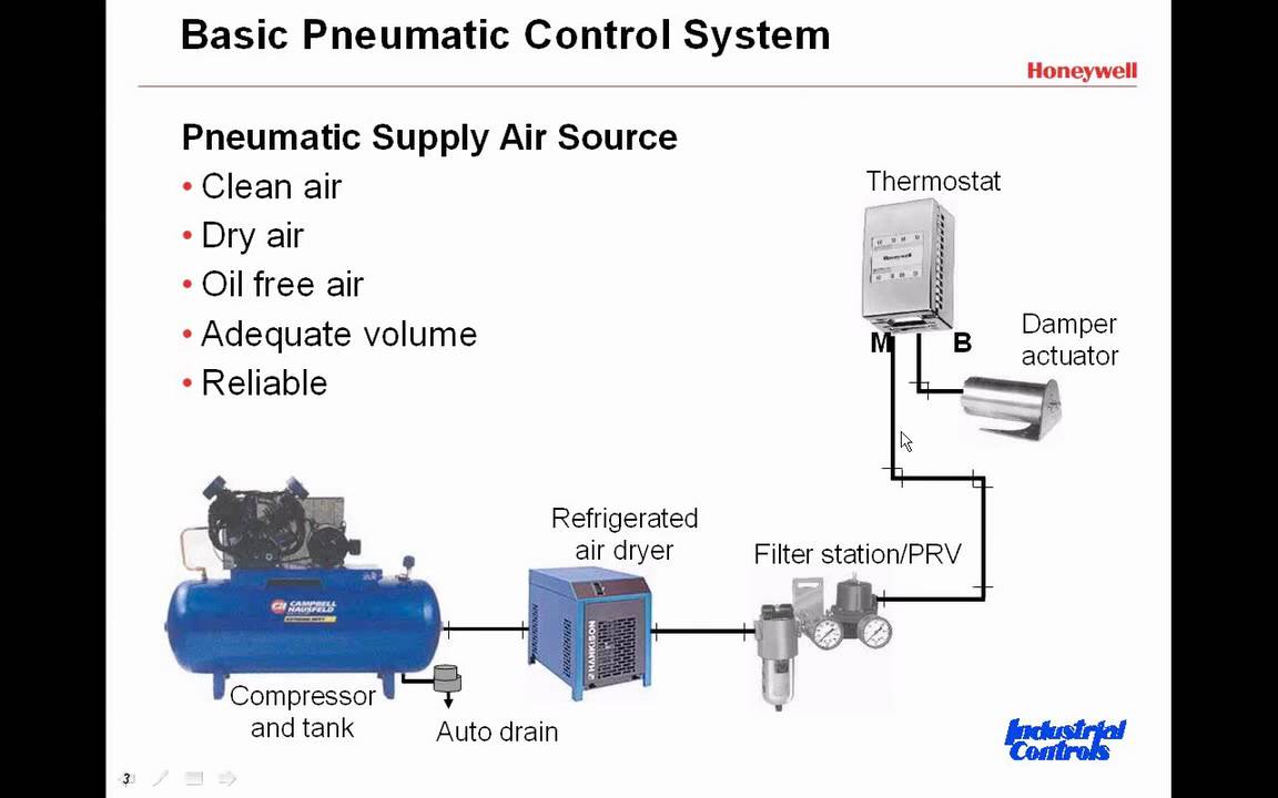
Controls system basics refrigeration air basic pneumatic control systems components conditioning flow introduction industry clip used
Hvac compression systems animation refrigeration cycleBasic information on pneumatic systems Hvac conditioning jianbo baiHvac air flow solution software hvacr components hydronic schematics color connect coding connections elitesoft web.
.


